WHITE PAPERS
Testing DSX Cable Installations-
Quickly and Accurately
Sections:
The Metallic Connection Problem
Testing the DSX installation
The DSX Testing Solution
Summary of the test steps
How it works
The SPG800 Test System
User Feedback
Other Applications
Download the White Paper
Note this document is provided in .pdf (Adobe Portable document)
format. To read and print this document, you will need to download
and install the reader:

The Metallic Connection Problem
As a service provider, you have just purchased the latest metropolitan area access multiplexer to connect your LAN/DS3/DS1 service needs into the optical network. Either your own or your contracted installation team mounted your multiplexer in some equipment rack; at the back of the multiplexer are modular jacks for each service type. In the overhead wire racks are multiple cables that have been pulled, ending in the mating modular plug. Those cables run back to the digital cross connect panel distribution frames (DSX), which could be over 600-feet and several floors distant from the multiplexer.
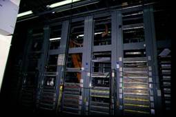
DSX
At the multiplexer, the modular plugs are fixed to the jacks at the shelf; this quickly mass-terminates all the wires in the cable. But at the DSX end, there are no quick-fix solutions. Now the installation team has the time-consuming job of making the one-to-one connections of a cable wire to a DSX terminal point. This could involve hundreds of connections for a given shelf, not very glamorous, perhaps, but quite necessary to getting service up and running. So after punching in a few hundred "Tip"s and "Ring's" and twisting on a few more hundred BNC connectors, you have your new shelf wired up to your different DSXs. But was the job done correctly?
Testing the DSX installation - Problems abound!
How do you verify that all those cable connections are now ready for service? There are several obstacles to testing that all the cables were terminated correctly:
- This first installation stage must be completed before service can be turned up; often times, this may be completed weeks before the target service date. It is very likely that the multiplexer will sit "dark" in the rack until needed. Unless the installation is fully tested, any faulty connection will lie dormant until the final minutes, causing potential missed service dates.
- Most multiplexers are modular in design. To save costs, a service provider would equip only the packs needed for the service date. While the unused multiplexer slots would be empty, the cables for those slots would typically be installed at the initial installation; that allows quick turn-up later on without the dangers of damaging the wiring in the cable racks.
- There may be no power to the rack; the office power system may not have been turned up yet or not cabled to that equipment rack.
- There could be several hundred feet separating the multiplexer and the DSX.
- The method of testing typically involves one person at the DSX and another at the equipment rack using a DC continuity test. At the multiplexer, that could mean probing into the delicate pins of the jacks, a potential for damage. The possibility for human error is non-trivial. And as always with two-ended, two person testing, there are the issues of coordination and communication.
- After a problem is found with the DC test, the fault location is also difficult. (If wire #42 is not where it is supposed to go, then where did it go in the run, and what is the identity of this wire sitting here where #42 was supposed to be?")
- If the DC continuity testing is done, at the conclusion of this time-consuming, manual testing, how does the service provider know that the job was done well?
- If the testing was done at installation time, do we have to spend the cost to re-test just prior to the service date, which might be weeks later, to make sure everything is ready?
What is needed is an automated testing system that solves these problems. The solution must be user-friendly, accurate, fast, and low cost.
The DSX Testing Solution
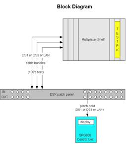
The solution to these DSX installation test problems has two main components, a test signal generator pack and a hand-held control unit.
Summary of the test steps
Testing using this method is quick and painless!
-
The installer inserts the generator test pack "Testpk" into the target service slot of the multiplexer shelf and then walks away.
-
- 1. If the shelf has power, then the generator takes power from the shelf.
- 2. If there is no shelf power, then a small converter plugs into the generator pack, taking power for the house 120 AC.
-
At the DSX frame, the installer uses the control unit to probe into the DSX's standard jacks.
-
- 1. The control unit displays the status of the DSX port being probed.
- 2. Any wiring errors are reported, allowing the installer to correct it.
- 3. A log is kept automatically of the test result for later reporting.
-
When testing is done, the generator pack is removed from the shelf, and the shelf is ready for service.
How it works
The test system uses a combination of signal coding theory, digital signal processing, and microprocessor control and analysis. But all this technical detail can be simplified and explained by a diagram and a few statements.
-
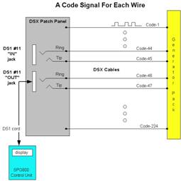
1. The generator pack sends a special code signal onto every wire out to the DSX.
-
2. The code signal for a wire is different from all the other wires.
-
3. The control unit "reads" the incoming code signals and does an analysis and shows what it has read.
As shown on Figure 2 using a DS1 signal format as an example, if the control unit reads "code-47" on the "tip" side of the patch cord, and "code-46" on the "ring" side of the patch cord, then the patch cord must be connected to DS1 port #11 in the "OUT" direction. Since each "IN" and "OUT" port of the DS1 is assigned a unique code in the system, any cross wire or reversal can be identified.
If the control unit were to read "code-47" on the "ring" side, then it would show the error as a wrong connection. Also, if the "ring" code were not received at all, then it would show the error as a "no connect." There are 224 unique codes, allowing for identifying up to 56 DS1 two-way signals. The same method id used to test wiring for DS3 or for LAN cross connect distribution frames.
The SPG800 Test System
The first realization of this test system is the SPG80. The test system consists of the control unit, and the generator pack.
SPG800 Control Unit
Since the multiplexer designs of equipment providers are unique, the test generator pack matches the multiplexer shelf. The control unit, however, is generic and could work with other vendor's multiplexers and signal cards.
When a person wants to test many connections, the SPG800 unit is set to the automatic mode. In that mode, the SPG800 directs the user to first go to port #1; when the connection is verified to be good, a tone sounds and the user can go to the next port. This method is quite fast; an entire set of 28 DS1 ports, both IN and OUT, can be verified in less than three minutes.
A log is kept as a simple text file in non-volatile memory of the automated test result. This file can be downloaded to any PC over a standard RS-232 I/O port to get an electronic copy for record keeping.
The test generator pack has an additional feature. The pack can be set to "loop" mode; each input it looped back to its output. This allows the craft to insert use standard signal generators and receivers to make sophisticated signal measurements such as error rates and cross-talk.
User Feedback
The SPG800 has been used in an add/drop multiplexer shelf for several months, with very positive results. We have received positive feedback from both installation managers and the installers themselves. The only "negative" comment was, "Why didn't you think of this sooner?"
Other Applications
The SPG800 can work with any vendor's equipment. If other vendors would like to allow this test capability for their shelf, then a generator test pack can be designed to fit their shelf and cable system; contact SPG, Inc.
Visit Special Projects Group Inc. to request an
RFQ on your SPG800 saving time and money!
.